Connex Pro Addon Board
Precautions & Tips
Do NOT mount the controller near any heat source! This will causing failure of the internal components. The ABS housing can withstand greater heat then the internal components.
Connex Pro Wiring
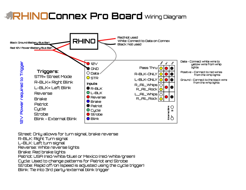
Input Channels
These are the input channels that trigger different functionailty based on what channel is triggered with 12 volts.
- 12 Volt (12v)- Power to Connex
- Use a 16 awg wire along with a fuse and relay to supply power to the Connex board.
- Switch Recommended - On/Off switch
- Ground (GND)
- Use a 18awg wire to connect to the ground circuit.
- Data (DATA)
- Connect this to the data output on the bluetooth controller (White wire).
- Street Only Mode (STR)
- When enabled turns all lights "black" or off and only allows turn signal, braking and reverse functionality to work Needs 12v to activate
- Switch Recommended - On/Off switch
- Right Blink Trigger (R-BLK)
If connecting halos make sure to plug into 5v regulators
- 12 volts activates RIGHT turn signal functionality.
- Switch Recommended - On/Off/On switch (Combine Left/Right Turn Signal to this switch)
- Left Blink Trigger (L-BLK)
If connecting halos make sure to plug into 5v regulators
- 12 volts activates LEFT turn signal functionality.
- Switch Recommended - On/Off/On switch (Combine Left/Right Turn Signal to this switch)
- Reverse (REVERSE)
- 12 volts activates reverse functionality which turns L_ALL / R_ALL white. Any products connected to the L_ALL / R_ALL will turn solid white.
- Switch Recommended - On/Off switch OR Tap into existing reverse trigger
- Brake (BRAKE)
- 12 volts activates L_ALL / R_ALL braking functionality. Any products connected to the L_ALL / R_ALL will flash Red 5 times then turn solid red when this is triggered.
- Switch Recommended - N/A - Tap into existing tail light brake trigger
- Patriot (PATRIOT)
- 12 volts activates PATRIOT mode patterns.
- Patriot Mode are custom patterns NOT available on the controller that have RED/White/Blue for USA and RED/White/Green for Mexico.
- In order to change the pattern, you must use a momentary switch or an on/off switch.
- Switch Recommended - On/Off switch
- Cycle (CYCLE)
- Momentary 12 volts will change the patterns of PATRIOT and S.O.S. modes or change the speed of STROBE mode when triggered.
- Switch Recommended - Momentary switch OR On/Off
- Strobe (STROBE)
- 12 volts activates STROBE mode which flashes patterns/color from the bluetooth controller.
- There are 6 options of strobe speed. Use the CYCLE momentary switch to cycle speed of the patterns.
- Switch Recommended - On/Off switch
- 3rd Party Blink Input (BLINK)
- A 3rd party turn signal kit is not required, rather can work with the Connex system.
- 12 volts will disable the internal Connex blinking feature.
- Tap into your existing turn signal module (Ex: Corbin, XTC, etc.). Tie BLINK wire to 12V wire (Red) when wanting to use an external turn signal module.
S.O.S. mode is a triggered when both PATRIOT and STROBE modes are ON. This mode alternates flashing colors on ALL channels. Use CYCLE to change the patterns available in S.O.S. mode.
Switch Recommendation Summary
- On/Off - Power Connex and Controller
- On/Off - Street Only mode
- On/Off/On - Left/Right Turn Signal
- On/Off - Reverse (optional if tapping into other lights or reverse trigger)
- N/A - Brake (tap into existing brake trigger)
- On/Off - Patriot (Enabling both Patriot and Strobe will trigger SOS Mode)
- On/Off - Strobe (Enabling both Patriot and Strobe will trigger SOS Mode)
- On/Off OR Momentary - Cycle patterns for Patriot, S.O.S. and Strobe
A Switch panel is an easy way to achieve all Connex functionality. Consider using our switch panel options when installing the Connex Pro add-on board.
Output Channels
These are the channels you want to connect your whips, rock lights, LED Strips and halos to based on the functionailty you want them to do. This system is highly customizable, the below options is what comes standard. Contact us for more custom options
If none of the below outputs are triggered, by default all products will show what the user has set within the LED Chord app.
ALL output channels are affected by PATRIOT, STROBE, and S.O.S. modes.
- Pass Through Channel (PASS THR)
- This channel was intended to be used for rock lights or LED strips.
- This channel uses the pattern/color set on the bluetooth controller through the LED Chord app.
- This channel does NOT get affected by turn signal, brakes or reverse functionality (if enabled)
- Can be used for any products, contact us for more information on customization.
- Right Blink Only Channel (R-BLK-ONLY)
- This channel was intended for rock lights and/or halos.
- This channel gets affected by RIGHT turn signal ONLY.
- Our Rock lights can be installed in a variety of locations including on the front of a vehicle to be used as a turn signnal
- Can be used for any products, contact us for more information on customization.
- Left Blink Only Channel (L-BLK-ONLY)
- This channel was intended for rock lights and/or halos.
- This channel gets affected by LEFT turn signal ONLY.
- Our Rock lights can be installed in a variety of locations including on the front of a vehicle to be used as a turn signnal
- Can be used for any products, contact us for more information on customization.
- Left All Channel (L-ALL)
- This channel was intended for whips.
- This channel gets affected by LEFT turn signal, brakes and reverse functionality (if enabled).
- Can be used for any products, contact us for more information on customization.
- Right All Channel (R-ALL)
- This channel was intended for whips.
- This channel gets affected by RIGHT turn signal, brakes and reverse functionality (if enabled).
- Can be used for any products, contact us for more information on customization.
Relay Output Channels
These are 12 volt left and right relay output channels. These are used ONLY to trigger relays.
Always Trigger a Relay!
Max amperage of 4 amps, connect the output to a relay when triggering external LED lights from the Connex board. Never power lights directly.- Left Relay Output
- This is used to trigger a relay to turn on 12 volt LED lights when the LEFT turn signal blinker is on.
- Right Relay Output
- This is used to trigger a relay to turn on 12 volt LED lights when the RIGHT turn signal blinker is on.